TanDEM-X: Reflector Information
RetroReflector Array (RRA) Characteristics:
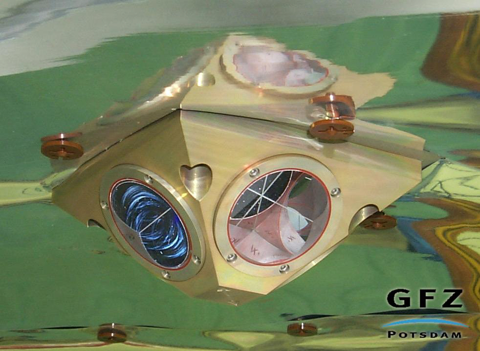
Courtesy of GFZ
The laser retro reflector for TanDEM-X is of the CHAMP design, a simple passive payload instrument consisting of four prisms to reflect short laser pulses back to the transmitting ground station. This enables the measurement of the direct two-way range between ground station and satellite with an accuracy of 1 to 2 cm.
TanDEM-X Retroreflector Information Form
(from TerraSAR-X Retroreflector Information Form 31 January 2007):(from http://ilrs.gsfc.nasa.gov/satellite_missions/ilrssupretro.html)
Satellite name Name: TanDEM-X
Sponsor: German Aerospace Center (DLR)
Contact for retroreflector information: Ludwig Grunwaldt (GFZ Potsdam)
Phone number: +49-331-2881733
E-mail address: grun@gfz-potsdam.de
A prerequisite for accurate reduction of laser range observations is a complete set of pre-launch parameters that define the characteristics and location of the LRA on the satellite. The set of parameters should include a general description of the array, including references to any ground-tests that may have been carried out, array manufacturer and whether the array type has been used in previous satellite missions. So the following information is requested.
1. Array type:
Pyramid-shaped 4-prism array of CHAMP type. For details please refer to http://ilrs.gsfc.nasa.gov/docs/rra_champ.pdf
2. Array manufacturer: GFZ Potsdam
3. Link (URL or reference) to any ground-tests that were carried out on the array:
4. Other missions using this LRA design and/or type of cubes: CHAMP, GRACE
For accurate orbital analysis it is essential that full information is available in order that a model of the 3-dimensional position of the satellite centre of mass may be referred to the location in space at which the laser range measurements are made. To achieve this, the 3-D location of the LRA phase centre must be specified in a satellite fixed reference frame with respect to the satellite's mass centre. In practice this means that the following parameters must be available at mm accuracy or better.
5. 3-D location (possibly time-dependent) of the satellite's mass centre relative to a satellite-based origin:
Satellite CoG location (in-orbit, wet, boom deployed) within mechancal build system:
Xm= +2275.7
Ym= -14.2
Zm= +6.4
Origin: geometrical center of the separation plane
Xm - towards the positive launch direction
Ym - forming a right-handed Cartesian system with Xm and Zm
Zm - perpendicular to the SAR antenna radiating plane
6. 3-D location of the phase centre of the LRA relative to a satellite-based origin: LRA optical reference point (intersection of the optical axes of all 4 prisms within the array) in body-fixed satellite system coordinates:
Xb= -1307.7
Yb= -212.1
Zb= +947.6
Origin: satellite center of mass (in-orbit, wet, boom deployed)
Xb - parallel to Xm, positive in nominal flight direction
Yb - forming a right-handed Cartesian system with Xb and Zb
Zb - in nominal flight orientation pointing towards nadir
However, in order to achieve (6) if it is not directly specified (the ideal case) by the satellite manufacturer, and as an independent check, the following information must be supplied prior to launch.
7. Position and orientation of the LRA reference point (LRA mass-centre or marker on LRA assembly) relative to a satellite-based origin: see 6.; these coordinates refer directly to the satellite center of mass!
8. Position (xyz) of either the vertex or the centre of the front face of each corner cube within the LRA assembly, with respect to the LRA reference point and including information of amount of recession of front faces of cubes: for position and orientation of the prisms within the array see http://ilrs.gsfc.nasa.gov/docs/rra_champ.pdf
9. Orientation of each cube within the LRA assembly (three angles for each cube): for position and orientation of the prisms within the array see http://ilrs.gsfc.nasa.gov/docs/rra_champ.pdf
10. Shape and size of each corner cube, especially the height: Clear aperture of front face 38 mm; vertex length 28 mm
11. Material from which the cubes are manufactured (e.g. quartz): Fused quartz
12. Refractive index of the cube material, as a function of wavelength ? (micron): 1.461 @ 532 nm
13. Dihedral angle offset(s) and manufacturing tolerance: -3.8 arcseconds
14. Radius of curvature of front surfaces of cubes, if applicable: + 500 meters
15. Flatness of cubes' surfaces (as a fraction of wavelength):
16. Whether or not the cubes are coated and with what material: Reflecting surfaces coated by aluminum; front face uncoated